1. When the outer circle is finished, there are chaotic ripples on the circumferential surface
cause:
- 1. The raceway of the main shaft rolling bearing is worn.
- 2. The axial clearance of the main shaft is too large.
- 3. When the workpiece is supported by the tailstock for cutting, the top sleeve is unstable.
- 4. When the workpiece is clamped by the chuck for cutting, the workpiece is unstable due to the loose fit between the inner thread of the flange hole of the chuck flange and the centering journal thread at the front end of the spindle, or the claw is shaped into a horn hole, which makes the workpiece clamping difficult. stable.
- 5. The square tool holder is deformed by clamping the tool, causing poor contact between the ground and the surface of the bottom plate of the upper tool holder.
- 6. The gap between the sliding surfaces of the upper and lower tool rests (including the slide) is too large.
- 7. The three supports of the tool box and the slide box bracket are not on the same axis, and the rotation is stiff (jamming phenomenon).
Solution:
- 1. Replace the rolling bearing of the main shaft.
- 2. Adjust the clearance of the thrust ball bearing at the rear end of the main shaft.
- 3. Check the tailstock tip sleeve, the shaft hole and the clamping device. If it fails, the shaft hole can be repaired first.
- 4. Change the clamping method of the workpiece, and use the tailstock to support it for cutting.
- 5. Scrape, grind and trim the joint surface of the bottom plate of the square tool holder to make it reach a uniform full contact.
- 6. Adjust the plug iron pressure plates of all guide rail pairs to make them fit evenly and shake smoothly and lightly.
- 7. Check each support, remove and reassemble if necessary.
2. On the outer surface of the fine turning, ripples appear repeatedly at a certain length
cause:
- 1. The vertical knife pinion of the slide box is not properly meshed with the rack.
- 2. The polished rod is bent or the mounting holes of the polished rod, the screw rod and the knife rod are not on the same plane.
- 3. A transmission gear in the slide box may be damaged, or the kneading caused by the pitch vibration is incorrect.
- 4. The shaft in the headstock and the tool box is bent or the gear is damaged.
solution:
- 1. Adjust the meshing clearance and make the rack and pinion mesh on the full width of the tooth surface.
- 2. The polished rod should be removed and straightened; the three holes should be coaxial and on the same plane during assembly.
- 3. Check and correct the transmission gear in the slide box. If it is damaged, it must be replaced.
- 4. Check the drive shaft and gear, straighten the drive shaft, and replace the damaged gear.
3. The outer diameter taper is out of tolerance after the cylindrical workpiece is processed
cause:
- 1. The non-parallelism of the headstock spindle centerline to the sliding guide rail is out of tolerance.
- 2. The inclination of the bed guide rail is out of tolerance or deformed after assembly.
- 3. The guide rail surface of the bed is seriously worn, and the non-straightness in the horizontal plane when the carriage moves and the inclination when the carriage moves is out of tolerance.
- 4. Because the center line of the taper hole of the main shaft and the center line of the taper hole of the top sleeve of the tailstock are not on the same straight line.
- 5. The influence of the blade is not wear-resistant.
- 6. The temperature rise of the bedside box is too high, causing thermal deformation of the machine tool: friction heat is generated due to movement, and the heat is absorbed by the lubricating oil, becoming a larger secondary heat source, and the heat is transferred from the bottom of the bedside box to the bed. , the head of the bed, the temperature of the joint part of the bed rises, expansion occurs, and the machine tool is thermally deformed.
Solution:
- 1. Re-calibrate the installation position of the center line of the headstock spindle so that the workpiece is within the allowable error range.
- 2. Re-calibrate the inclination of the bed guide rails by adjusting the horn.
- 3. When the non-straightness of the sliding plate movement in the horizontal plane and the inclination of the sliding plate movement are small, the guide rail surface has no large area scratches, which can be repaired by scraping the guide rail.
- 4. Adjust the screws on both sides of the tailstock to eliminate the taper.
- 5. Dress the tool and correctly select the spindle speed and feed.
- 6. Properly adjust the oil supply of the front bearing lubricating oil of the main shaft, replace the appropriate lubricating oil, and check whether the oil intake of the oil pump is blocked.
4. After finishing turning, the end face of the workpiece is convex
cause:
- 1. The non-parallelism of the slide movement to the center line of the headstock spindle is poor.
- 2. The upper and lower guide rails of the slide are not vertical.
Solution:
- 1. Correct the position of the spindle centerline of the headstock. On the premise of ensuring that the positive taper of the workpiece is qualified, the spindle centerline deviates forward, that is, toward the tool holder.
- 2. Scrape and grind the guide rail surface of the slide, and make the outer end of the upper guide rail of the slide deflect towards the headstock.
5. When turning threads, the pitch is uneven and chaotic
cause:
- 1. The screw of the machine tool is worn and bent, the wear of the opening and closing nut is not coaxial with the screw and the meshing is poor, the gap is too large, and the opening and closing nut is unstable when closed due to the wear of the dovetail guide.
- 2. The clearance of the transmission chain from the main shaft through the hanging wheel is too large.
- 3. The axial clearance of the screw is too large.
- 4. The male and inch handles are wrongly hung, the fork is in the wrong position, or the hanging wheel on the hanging wheel frame is wrongly hung.
Solution:
- 1. Straighten the screw rod, adjust the gap between the screw rod and the opening and closing nut pair, and repair and scrape the dovetail guide rail to ensure the stability of the opening and closing nut when it is closed.
- 2. Check the meshing clearance of each transmission part. Anything that can be adjusted, such as hanging wheels, should be adjusted.
- 3. Adjust the axial clearance of the screw and its movement.
- 4. Check whether the handle, connecting fork and hanging wheel are correct, and correct it if it is wrong.
6. The workpiece produces an ellipse or an edge circle
cause:
- 1. The spindle bearing clearance is too large.
- 2. The ellipse of the spindle journal is too large.
- 3. The main shaft bearing is worn, or the precision of the final gear of the main shaft is out of tolerance, and there is vibration during rotation.
- 4. The outer diameter of the main shaft bearing sleeve is elliptical or the shaft hole of the bedside box is elliptical, or the matching clearance between the two is too large.
- 5. The thimble tip of the machine tool is ground off, or the thimble hole of the workpiece is not round.
solution:
- 1. Adjust the clearance of the main shaft bearing; if the lathe is working at high speed, the adjusted clearance should be slightly larger, and if it is working at low speed, the clearance should be smaller. If the spindle clearance is adjusted at low speed, the shaft holding phenomenon may occur during high-speed work. Therefore, it should be adjusted according to the standard speed range of the lathe for daily use, and the general clearance should be between 0.02 and 0.04 mm.
- 2. Grind the journal of the main shaft to meet the requirements of roundness.
- 3. Scrape and grind the bearing, replace the rolling bearing or the final gear.
- 4. If the out-of-roundness of the shaft hole is particularly poor, it should be rounded and straightened first, and then repaired by “partial nickel plating”; if it is a sliding bearing, a new bearing sleeve must be replaced.
- 5. Grinding thimble or workpiece thimble hole.
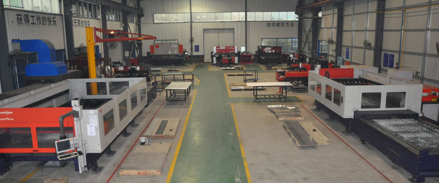
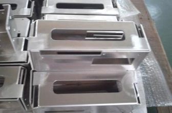
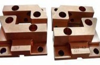
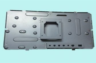
Pintejin Sheet Metal shop offers a cost-effective solution for a wide range of industries with our custom metal stamping and custom sheet metal fabrication capabilities. Our stampnig operations include a variety of sheet-metal forming manufacturing processes, such as punching, blanking, embossing, bending, flanging, and coining. Our professional, experienced and well-trained engineers can execute the complex metal stamping operations with precision and accuracy.
No matter what your metal fabrication needs are, Pintejin can offer the right solution: from single sheet metal part or sub-assembly of stamped metal parts to turnkey solutions for mechanical and electrical assemblies. We have the technology, equipment and the experience to fabricate customised metal products from aluminium sheet metal fabrication, steel, zinc plated steel, stainless steel sheet metal fabrication, brass and copper. Designs that require CNC machining of surfaces or components can be accommodated. We can supply polished, galvanized, zinc coated or powder coated finishes for any sheet metal work or stamped metal components. Coupled with our accurate and reliable metal fabricating equipment, we guarantee precision and repeatability in custom sheet metal work. You’ll be taking advantage of the best sheet metal fabrication china can produce.


