Sheet Metal Design Assistance
In 3D software, SolidWorks, UG, Pro/E, SolidEdge, TopSolid, CATIA, etc. all have sheet metal parts, mainly through the editing of 3D graphics to obtain the data required for sheet metal parts processing (such as unfolding drawings, bending Line, etc.) and provide data for CNC Punching Machine/Laser, Plasma, Waterjet Cutting Machine/Combination Machine and CNC Bending Machine, etc.In order to meet the requirements of product function and appearance, the design of sheet metal should ensure that the stamping process is simple, the stamping die is easy to make, the sheet metal stamping quality is high, and the size is stable.
Online Sheet Metal Design Services – Custom Project Design & Parts Drawings Assistance
SHEETMETAL.WIKI – Pintejin Group is a China sheet metal company with more than 15 years of experience in product design and industrial parts manufacturing. With a highly-skilled design and engineering team, our online Sheet Metal Design Services can turn your concept into reality, ranging from mechanical components to parts used in aerospace, automotive, defense, electronic, electrical, entertainment, food and beverage, health, industrial automation, machinery, medical, oil, energy, power, sporting goods, telecommunications, transportation,office furniture, HVAC, appliance and food service equipment and more industries. Even if you just have an idea of the final product, please tell us your detailed requirements or submit a sample, we’ll deliver a professional sheet metal product design drawing based on your customization.
20 Years Of Design Experience In Sheet Metal Design
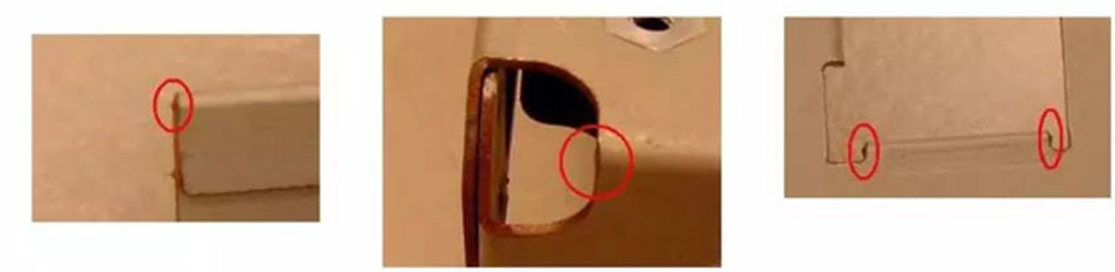
Lesson #1: Clearly Identify Burr Direction
R angle and burrs will be generated when the sheet metal is blanked and punched.
Especially after the mold is worn out in the first stage of mass production, the burrs will be more serious, and even the fingers will be cut.
Therefore, when drawing a mold to make a mold, it is necessary to clearly mark the direction of the burr according to the function.
Lesson #2: Via Spacing And Thermal Via Design
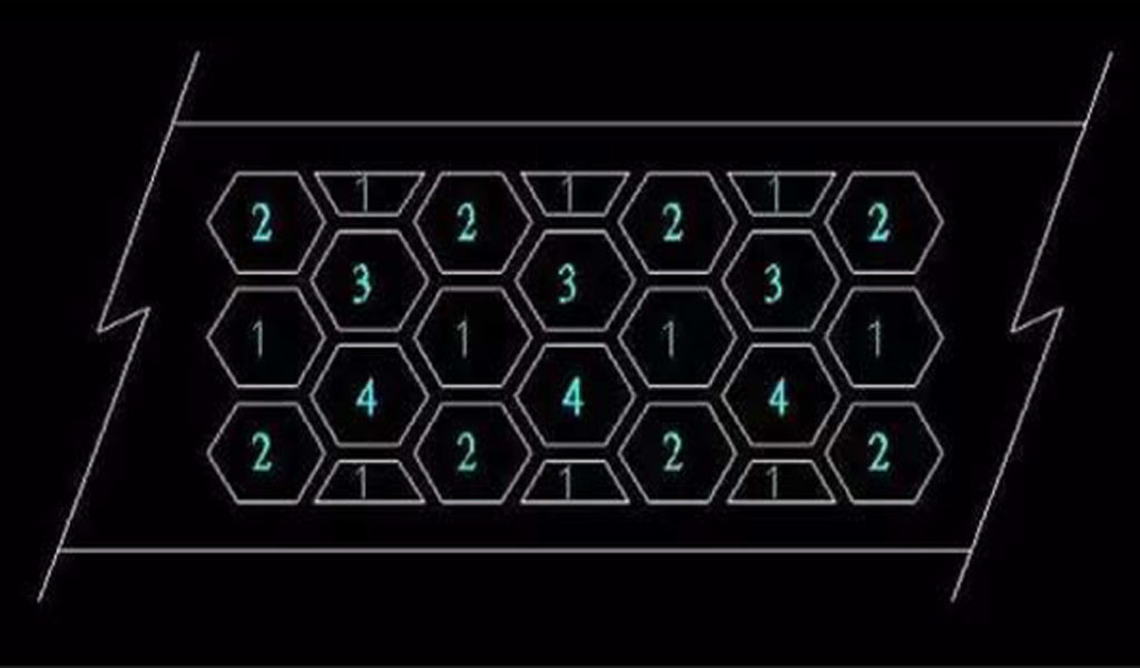
- For two adjacent holes, the shortest distance from the edge of the hole to the edge of the other hole should preferably not be less than 1.5 times the thickness of the material, otherwise the master mold will easily crack and the production line will be broken. Broken wires, mold repairs, etc. are the culprits that increase the cost and reduce the profit. If it is absolutely necessary to be less than 1.5 times the thickness of the material, the tabbing method must be used.
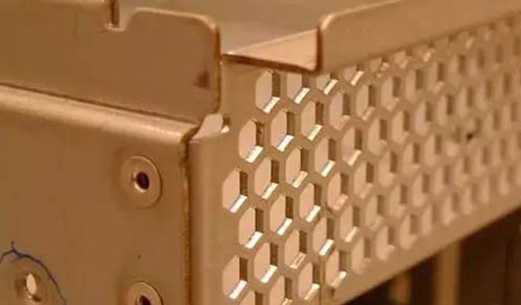
- In the mold making, the round hole is the strongest and best for manufacturing and maintenance, but the opening rate is low.
- The square hole has the highest opening rate, but because it is at a 90-degree angle, the corner edge is easy to wear and collapse, resulting in the need to repair the mold and stop the line. The hexagonal Honeycomb, whose 120-degree angle is greater than 90 degrees, is stronger than the square hole opening, but the opening rate is a little worse than the square hole at the edge.
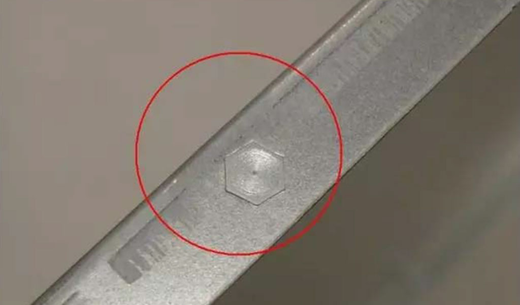
Lesson #3: Protrusion-To-Bend Distance
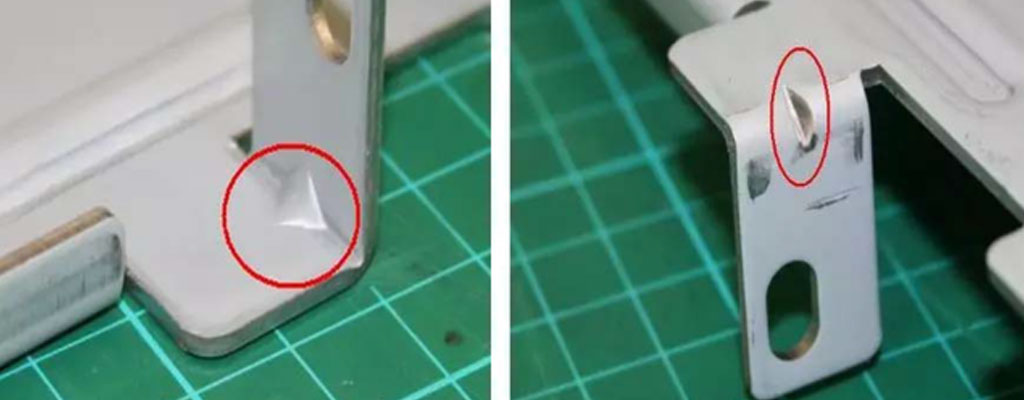
When bending, the parts on the bottom edge such as studs or internal protrusions should not be too close to the bending edge, preferably more than 10mm, otherwise the corners below the protrusions have no male die stamping, and the R angle will be higher than the R angle on the left and right sides. Big corners.The R angle is not continuous and will affect the appearance.The solution is to punch out an appropriate length of indentation on the fold line before bending, which will improve its appearance.
Lesson #4: Hole To Bend Edge Distance
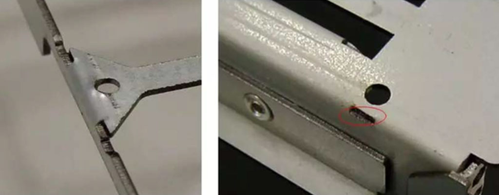
When bending, the opening on the side wall should not be too close to the bending edge, preferably more than 3mm, otherwise the opening will be deformed due to bending. The solution is to punch out a long hole with the same length as the opening and 1.5 times the thickness of the material before bending, which can cut off the pull without affecting the appearance of the opening.
Lesson #5: Key Points For Screw Hole Design
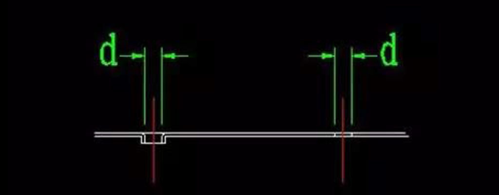
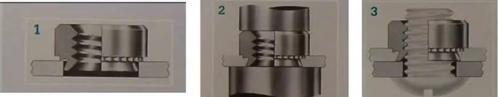
There are generally three ways to fix the screw
- Direct punching (through hole) or drawing hole (drawing hole) on the plane of sheet metal parts, using self-tapping screws. Self-tapping screws are preferably triangular self-tapping screws, and the problem of slippage will not occur. Only the driving force will be a little heavier than non-triangular self-tapping screws. If it is screwed with a diameter of 3mm, the hole diameter d should be between 2.4 and 2.5mm. If the screw is locked with a diameter of 4mm, the aperture d should be between 3.4 and 3.5mm.
- Punch through holes or drawing holes on the plane of the sheet metal parts, and then tap the screws to tap the M3 or M4 mechanical teeth. If the screw is locked with a diameter of 3mm, the hole diameter d should be 2.6mm before tapping. If the screw is locked with a diameter of 4mm, the hole diameter d should be 3.6mm before tapping. If the thickness of the material used is 1.0~1.2mm, it is recommended to use a drawing hole instead of a through hole. Due to the 1.2mm material thickness, when tapping the M3 teeth, there are only 2.5 teeth, which is easier to slip.
- Punching through holes on the plane of the sheet metal parts and then riveting the ready-made fixing nuts (Self Clinching Nut). The hole diameter d of the riveted fixing nut is preferably the size recommended by the manufacturer. However, when riveting the nut (Self Clinching Nut), it must be noted that PEM (Penn Engineering & Manufacturing Corp.), a major manufacturer of Stand-off/Self Clinching Nut, has a special riveting machine, but it is processed one by one. Time consuming and expensive. Therefore, almost all processing plants use general punches for riveting. If the machine used unfortunately is a traditional punching machine, the problem of the nut falling off may occur. The reason is that the punching speed of the traditional punching machine is too fast, and the material of the workpiece has no time to fill the nut or the groove of the stand-off. The problem is completely undetectable from the appearance, but some nuts will fall off when the finished product is assembled. Therefore, the machine for riveting the fixed nut is best to choose the one that can adjust its punching speed.
Lesson #6: EMI Shrapnel Materials
Generally, the materials we often use when making EMI shrapnel are: tinplate, corrugated copper, stainless steel, etc.
- The surface of tinplate is plated with tin (Tin), and the hand sweat left after touching it is easy to cause rust. After cutting, the cutting surface is no longer treated and it is easy to rust. It is easy to stamp and form, and the cost is the lowest.But the elasticity is the worst. Due to its low carbon content, even heat treatment cannot increase its elasticity.
- Titanium copper has the best conductivity and the most expensive material cost. But it is the easiest to break, and has the problem of structural directionality. The directionality of the material must be noted during production. If necessary, the elastic qualitative treatment can be done to increase its elasticity.
- Stainless steel is currently the most used. No rust, not easy to break, but not easy to punch. The mold is easy to wear and the finished product is prone to burrs. In order to have good flexibility, it is necessary to do elastic qualitative processing.Otherwise, you will not be able to reply if you press your head. If you want Cost Down not to do elastic qualitative treatment, it is best to make a Stopper in an appropriate place to prevent the shrapnel from being over-pressed and unable to rebound and lose its meaning.
- Generally, after the sheet metal parts are bent, the metal material will protrude on both sides of the corner due to the extrusion material. The width is larger than the original size, and the protruding size is related to the thickness of the material used. The thicker the material, the larger the protruding point. In order to avoid this phenomenon, a semicircle can be made on both sides of the bending line in advance, and the diameter of the semicircle is preferably more than 1.5 times the thickness of the material. When the edge material is turned back, it is handled in the same way.
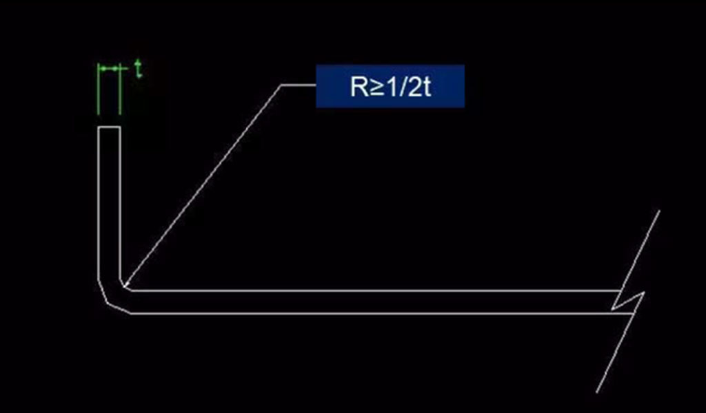
Lesson #8: Bend Radius
The internal R angle of the sheet metal part during bending is preferably greater than or equal to 1/2 of the material thickness.
Because if the R angle is not made, the right angle will gradually disappear after many times of stamping, and the R angle will naturally be formed.
After that, the length of one side or both sides of the R angle will be slightly longer.
Lesson #9: Bend Height
The bending height should preferably be greater than 3mm. (t: 1.0~1.2mm) Otherwise, the size will be unstable because the clamping size is too small.
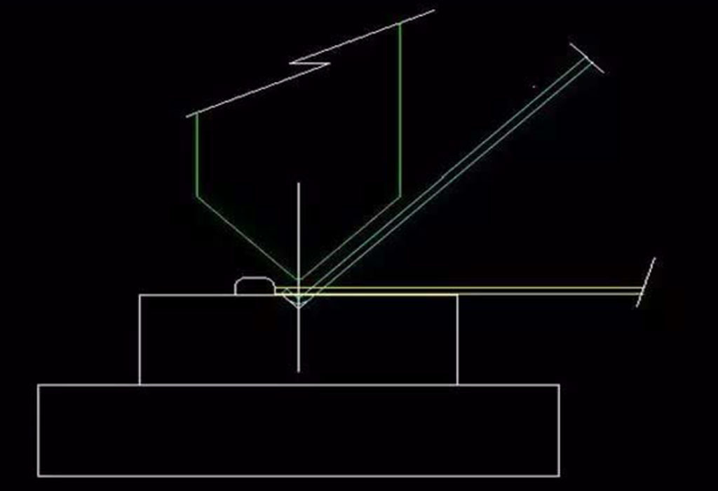
Lesson #10: Punch And Die Size
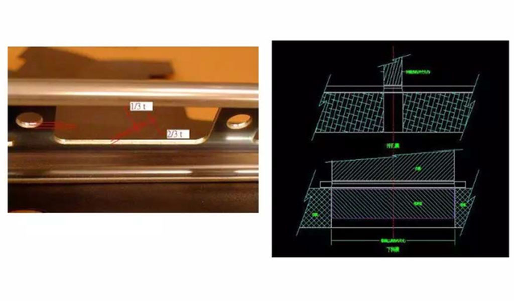
When the sheet metal parts are blanked and punched, the 1/3~2/5 of the cut section close to the male die punch is a flat cutting surface, while the 3/5~2/3 close to the female die is an oblique tear section. .
Therefore, the size of the aperture when making the mold or testing the size is based on the punch. When blanking, the outer dimension of the workpiece is based on the inner dimension of the master mold.
Lesson #11: Corner R Angle
At the corner of the edge of the sheet metal part, if there is no special requirement for a 90-degree angle, be sure to treat it as an appropriate R angle. Because the right angle on the edge of the sheet metal part can easily cause sharp points and cut the staff.
The right-angled tip of the master mold is prone to cracking due to stress concentration. The male mold is easy to crack at the tip, so that the mold must be repaired and the mass production is delayed. Even if it has not cracked for a long time, the R angle will be formed due to wear and tear, which will cause the product to have burrs and cause defective products.
Lesson #12: Bend Reinforcing Ribs
Sheet metal parts are easily deformed by force after bending. In order to avoid deformation, an appropriate amount of 45-degree reinforcing ribs can be added at the bend to increase the strength on the principle of not interfering with other parts.
Lesson #13: Rib Reinforcement
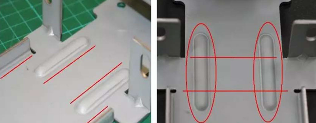
Generally, sheet metal parts are not easy to maintain their straightness when they are long and narrow, and are more easily deformed after being stressed.
Therefore, we can fold one side into an L shape or fold two sides into a mouth shape to maintain its strength and straightness. But often L and mouth shape cannot be connected from beginning to end, and what should I do when they are interrupted by some factors?
An appropriate amount of ribs can be added to increase its strength.
Lesson #14: Labels Are Marked On The Chassis

It is best to design the position and size of the required label before the chassis is opened, and you can mark the chassis first to facilitate the alignment of labels. The two most common markers are:
- Mark the “L” shape around the label, or the upper and lower sides of the left side, or the left and right sides of the upper side. This method is cheaper, but the label protrudes from the surface of the chassis and is easily scratched.
- According to the shape and size of the label, increase the size of 0.3mm, and make a dent of 0.2~0.3mm at the place where the label is to be attached.
No matter what method is used, a suitable angle can be selected from the four corners to make a 45-degree chamfer. Make the same 45-degree chamfer at the opposite position of the markings on the chassis. For foolproof use. Avoid stickers posted in different directions at different times or by different staff.
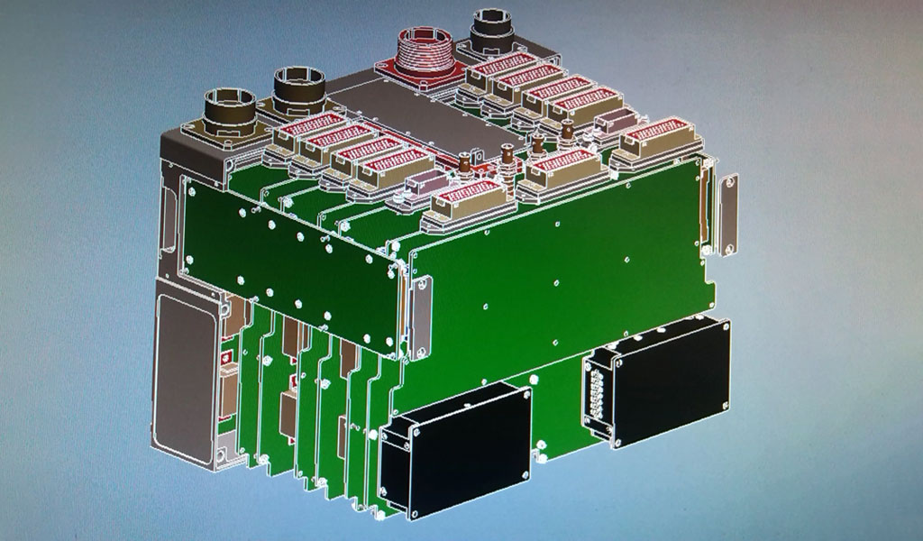
Lesson #15: Server Chassis Mid-Walls
- When the server chassis is on the rack, there are slide rails on the left and right sides to support it, so there will be no doubt of depression in the depth direction. But in the lateral aspect, the width of the rack is 450mm, after deducting the left and right slide rails of 10.mmX2, the width of the chassis is about 430mm. In such a wide, 1.2mm-thick sheet metal part, it is difficult to prevent the central part from sinking. The chassis itself includes front and rear walls. If the chassis with a longer depth is designed with a middle wall, the doubt of depression can be avoided. The design of the middle wall is best designed to be similar to the C-shaped steel structure and tightly combined with the two side walls and the bottom of the chassis, the strength of the entire system will be greatly improved. Even if it cannot be continued in a straight line, it is better to design a break than to cut off halfway.
- In addition to increasing the strength of the chassis and fixing the fan and air duct, the middle wall can effectively prevent EMl if it is in perfect contact with the inside of the upper cover, which greatly prevents the noise of the motherboard from emitting from the front. Therefore, it is best to avoid placing plastic parts on the middle wall, which blocks the contact with the upper part.
- Avoid the occurrence of acute angles where there is a break, and don’t forget to design a large R angle. In order to avoid the sharp angle against the upper cover when the upper cover is under heavy pressure, the appearance will be affected.
Lesson #16: Bump Location
- In the chassis assembly design, there are often two combinations, or more than 3 or 4 components. Common fixing methods include locking screws, pull studs, riveting or spot welding. When spot welding, the spot welding machine must have positioning points or positioning pins or fixtures to ensure the correct position. If there are already opposite screw holes and pull-nail holes when using screws or pull-nails, it is often not necessary to add a few more positioning holes for positioning. However, the hole diameter of the screw hole pull nail hole is generally designed to be larger for easy assembly.Therefore, the relative positions between parts are also prone to errors.
- In this case, it is recommended to use positioning bumps with small clearance for positioning. When doing tolerance analysis, it is more accurate to use the positioning point with smaller tolerance to do the benchmark calculation.
Lesson #17: Crack Relief
The bend between the flat surface and the bending surface should preferably have a crack relief groove, or the opening edge should be retracted after the bend. Otherwise, burrs will be produced, and the width of the narrow hole is preferably greater than or equal to 1.5 times the thickness of the material. Also, don’t forget or be lazy when drawing, and don’t mark the R angle. Right-angle or acute-angle mold male and female molds are easy to crack, and future line stops and mold repairs are additional losses.