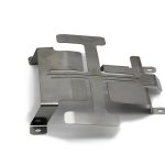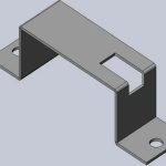
Sheet Metal Assembly
According to the specified technical requirements, the process of matching and connecting parts or components to make them semi-finished or finished products is called assembly.
There are many assembly methods for sheet metal parts. Sheet metal parts are widely used in various industries. Each industry has its own industry standard assembly methods. The following are sheet metal assembly methods widely used by Pintejin.
1.Buckle Assembly
Unlike the snap assembly of plastic parts, most sheet metal parts have no elasticity (except stainless steel SUS301), so the assembly of sheet metal parts cannot be completely completed by snap. Snap-fit is often used in conjunction with other sheet metal assembly methods, such as bolting, to provide quick assembly and reduce product assembly costs.
The structure of the clip assembly includes a clip and a slot. According to the guidelines of assembly-oriented design, it is best to add a 30° small bend to the front of the clip or slot to ensure smooth assembly.
2.Tie Rod (rivet) Assembly.
Pull stud assembly is to insert the pull stud into the corresponding holes of the two parts, and pull the pull rod with a pull stud gun until the pull stud sleeve is pulled out and expands, which is larger than the diameter of the hole, so as to achieve the purpose of assembling the two parts together.
Commonly used pull studs include flat head pull studs and round head pull studs. Flat head pull studs are used when the pull stud head cannot protrude from the surface of the part after the pull stud is assembled. In this case, the counterbore on the part needs to be enlarged. The size of the through hole of the sheet metal part is usually 0.1 to 0.3 mm larger than the size of the trunnion. In the design of the trunnion installation, the following points should be considered:
- a. Avoid overlapping the trunnion end with other components.
- b. The head surface of the flat tenon should be lower than the surface of the metal plate.
- c. Avoid interference with the nail gun.
3.Comes With Rivets.
The principle of self-riveting, the part with countersunk holes and the part with pumping holes are matched. After the two parts are matched, the punch will expand the pumping holes and fill the corner holes of the countersunk holes, so that the two parts are connected as a whole.
4.Mechanical Assembly Of Bolts
Bolted assembly of sheet metal parts means that when there are two parts to be connected, one of the parts is pulled out, the other is punched, and then the two parts are bolted together. There are three ways to bolt mechanical assembly of sheet metal parts.
a.Extraction Hole Assembly + Self-Tapping Screw;
Using self-tapping screws, the self-tapping screws are also threaded while being screwed in. For the inner diameter of the extraction hole, the size can refer to the manufacturer’s recommended specifications or the manufacturer of the self-tapping screw used.
b.Extraction Hole + Tapping Hole + Screw Assembly;
First, an additional tapping operation was added after dismantling; second, the two-part assembly was completed with ordinary machine screws instead of self-tapping screws.
c.Rivet Nut + Bolt Assembly;
The third method of assembly requires riveting the nut instead of the extraction hole and its tap.
5.Spot Welding
Spot welding is the welding of two sheet metal parts together at one point of contact. In the welding process, the surface of the metal plate is first cleaned, and then the two metal plates are aligned and connected together, pressed between the two columnar copper electrodes and pressed firmly. When enough current flows, a lot of heat is generated at the points of contact between the parts, causing the metals to be welded together in the central, hottest part of the joint.
Sheet Metal Assembly Standards
- Review the drawings before construction, and install the corner yard in strict accordance with the plan of the corner yard height required by the drawings. The height tolerance of the corner yard installation is ±1mm, the error of the corner yard position is within 5mm, and the special angle yard must ensure the required height.
- The thickness of the material used for the 2 corner yards should be the same.
- The installation of the reinforcing ribs should be according to the requirements of the drawings, the position and size tolerance should be within 5mm, and the strength of the back ribs should be increased and the flat surface of the board should not be deformed.
- The length of the reinforcing ribs, the way of playing the waist row holes, and the number of nails are the same – the batch board should be consistent.
- The distribution of reinforcing ribs should be uniform and the number should be avoided when reinforcing ribs.
- According to the actual material thickness of the seed nails, adjust the current size when seeding the nails, and pay attention to whether there are seed nails on the board surface after reinforcement.
- After the 7-angle code is installed, check the flatness of the board, and the flatness tolerance is 1000≤2mm, but it is not allowed to be wavy. .
- Only the boards after being straightened, assembled and inspected can enter the next process.
10 Assembly Rule Designs To Follow
1. Minimize The Number Of Parts
Find ways to combine parts. For example, many electronic equipment enclosures use living hinges instead of knuckle hinges. When routing, choose a molded guide feature, or use a thermoformed guide (like the old LazerTag gun). Speaking of minimizing parts count…
2. Built-In Fasteners
Where possible, build assembly features directly into the part instead of using screws. Snap fits are generally equally secure and can be assembled without tools. Sometimes screws are necessary, but sparing the use of fasteners can consume up to 50% of assembly labor. One thing to note: Snap fits can add to the cost of the injection mold, so be sure to design the part to be injection friendly.
3. Use Cots Parts
It’s great to be a product designer now. Many of our design issues have been resolved! Previously each thread had to be carefully engineered, but now there are hundreds of standard diameters and pitches to choose from.
This goes way beyond basic nuts and bolts. Cots parts cover most functional aspects of springs, pins, motors, microcontrollers, sensors, gear designs. Not only does this allow you to focus on unique challenges, it also means that the manufacturing team already has the tools and skills to assemble your design.
4. Use The Same Parts Throughout The Design And Product Line
WARNING ABOUT COTS PARTS: Just using standard screws is not enough. I once designed a robotic assembly where one part had M5 x 10 mm socket head cap screws and the other part was M4. Design the 5 x 12 mm hex head screws on the other part.
I had to switch between assembly tools constantly; it’s easy to get confused about which screw goes where, which is a really bad idea. Don’t follow my example: Standardize parts not only on each component, but across the entire product line. Where possible, a single tool should be used for the entire assembly.
5. Use Modular Design
An important application of cot parts and common parts is modularization, breaking down a design into smaller sub-assemblies, often for multiple products. Think about your first computer: you can put together some pre-assembled parts—motherboard, hard drive, graphics card, and it’s easy. As an added bonus, modular designs aren’t just great on the assembly line; they also help you extend the life of your product in the field by facilitating repairs and upgrades.
6. Create Unique Connections
Speaking of desktop computer assembly, another great example of assembly design can be found inside and outside computer cases from the 90s to the early 2000s. Each connection is mechanically unique. The mouse cable cannot be plugged into the monitor port. The power cable port is not to be confused with the keyboard cable.
Of course, I’m showing computers my current age on which everything can run using USB-C, which is much more DFA friendly (see Rule 4).
7. Give Parts Clear Direction
Related to the idea of unique connections is unique orientation: if the parts to be assembled have right and wrong orientations, figure out which way is right. Better yet, make it impossible for parts to be assembled the wrong way. For round parts this can mean just a notch, but for more complex shapes this can provide some creative design opportunities. Just don’t get too creative…
8. Make Parts Easy To Handle
Because assembly is now increasingly handled by robots. Automation costs are falling rapidly, and robots are appearing on more assembly lines. Design your parts for robotic gripper grasping and avoid very small or very flexible parts as much as possible. People on the assembly line will appreciate this too, no one likes inserting screws with a microscope.
9. Avoid Precision Parts And Non-Contact Areas
Likewise, helping robots and people on assembly lines by making parts durable during assembly. Rework can easily result if parts are too delicate, or if they are easily damaged by natural skin oils. Just think, if Bruce Banner is angry, can he still complete this assembly step in 10 seconds? If the answer is no, redesign.
10. Real-World Tolerance Design
Finally, make sure that custom parts can be easily manufactured. Tolerances accumulate, and small changes in each operation can cause a big problem, especially if your design can’t accommodate the changes.
Whenever possible, give your process as much room for error as possible. Yes, a mechanic can fit your part to within ten thousandths, but you’ll be unnecessarily introducing very expensive machining if needed . With 3d printing parts, the considerations are the same: even with laser sintering there are variations, and it’s worth considering how those tolerances fit together.